THE CHALLENGE Permanent magnet brushless motors can generate rotary and linear motion. They are known for their high torque density and high efficiency. They are also […]
THE CHALLENGE
Permanent magnet brushless motors can generate rotary and linear motion. They are known for their high torque density and high efficiency. They are also called brushless DC motors, brushless AC motors, permanent magnet synchronous motors, or servo motors. These electric machines generate torque (rotary) or force (linear).
For many applications in optics, scanning, metrology, optoelectronics, and tracking, the main challenge is to achieve constant and predictable torque/force. Traditional permanent-magnet brushless motors are subject to torque cogging, a disturbance resulting from the interaction between the permanent magnet and the slots interposed at the stator teeth. Cogging is cyclic torque at an angle that creates torque ripple (and corresponding speed ripple), going on to add a nonlinear element in motor control.
Various methods have been adopted over the years to minimize cogging, such as, for example, helical blades, helical magnets, special mechanical modifications, and electrical compensation in the motor controller. Most applications require constant motion with low loads.
THE SOLUTION
Slotless (slotless) motors are designed to optimize uniformity and achieve predictable torque output with minimal nonlinear effects. Commonly referred to as slotless motors if rotating and ironless if linear, slotless motors have air-wound coils. When properly arranged, these coils interact with the flow of permanent magnets to create force or torque. Cogging torque is eliminated by removing the discontinuity created by the stator teeth. Slotless technology is particularly effective with precision direct-drive systems because all torque is a function of phase current, and the motor does not generate unwanted or uncontrolled torque disturbances.
MOTOR TOPOLOGY
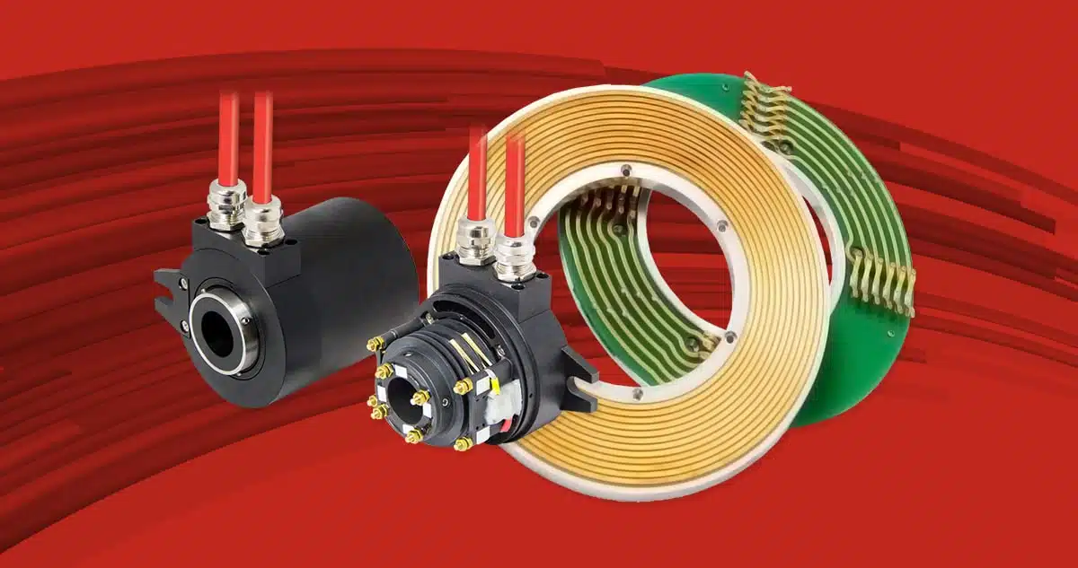
Permanent magnet brushless motors have two basic internal components: the permanent magnet assembly and the stator coil assembly. In the rotary version, these two components are called the rotor assembly and the stator assembly, while in the linear version, they are called the magnet bar and the forcer. The rotor/magnetic bar is a magnetic component consisting of permanent magnets applied to or immersed in a ferromagnetic structure. The stator/forcer assembles appropriately combined coils designed to generate a magnetic field with various phases, three in the most common realization.
The final part of this technical note is devoted to the comparison and differences between slotless and slotted rotary motors. The same principles also apply to ironless and ironcore linear motors.
ROTOR AND STATOR STRUCTURE
Permanent magnet rotor assembly
The rotor assembly is generally a steel ring or shaft to which magnets are attached, which may be mechanically distinct or form a solid ring with individual magnetic fields magnetized on it.
The number of poles is directly related to the number of permanent magnets in the rotor assembly. Sometimes, you may choose to count the number of north-south pairs; we will speak in this case of polar pairs. The total number of poles determines the transfer ratio between electrical frequency and mechanical speed. Generally, motors with fewer poles have higher mechanical speeds, while those with more poles are usually slower. Thanks to advances in modern wide-bandwidth electronics, it has been possible to increase the speed of even motors with many poles increasingly.

Stator group
Several electromagnetic phases must be properly excited for the motor to turn, which, in brushless permanent-magnet motors, are usually three. These electromagnetic phases are excited by current outputs generated by a motor controller. The motor controller typically uses feedback to monitor the rotor position and create the correct, current vector in the stator phases to achieve torque. Once the torque is created, it can be controlled along with speed and position to handle any motion control application.
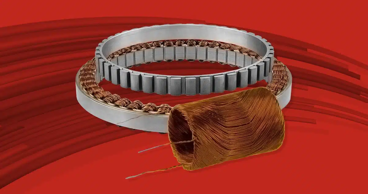
The stator assembly typically consists of soft iron blades with teeth that protrude radially. The spaces between these teeth are called slots and allow the insertion of the electromagnetic coil wire. This type of motor is called slotted.

In the example shown in Figure 2, the stator teeth and slots are clearly visible. The gray ring in the center of the motor is the rotor made of magnetic material with 36 magnetically inclined poles magnetized on it. Note that the poles have been approximated for representational reasons. The inclined configuration helps reduce cogging by axially alternating the magnetic field and compensating for the fundamental frequency of the cogging torque.
SLOTTED STATOR
Traditional configurations of a slotted stator are based on teeth that concentrate electromagnetic flux toward the rotor magnets and reduce the overall air gap of the magnetic circuit. Typically, each phase involves multiple teeth. Slotted motors are the most popular because they provide a good balance of output torque, motor constant, efficiency, and ease of manufacture. They usually provide the highest Kt (torque/Amper) momentum constant for a given motor size, high efficiency, and great acceleration with minimal inertia.
As explained earlier, the spaces between the stator teeth allow the wire of electromagnetic phases to be inserted. The slots are the main cause of cogging torque because they create discontinuous permeability as the magnets pass from one to the other. It is common practice to tilt or offset the stator teeth or rotor magnets to minimize the fundamental frequency of cogging torque.

The cogging torque of slotted motors typically ranges from 1 to 5 percent of peak torque, depending on the motor configuration. In applications with higher payloads, the minimum cogging torque is small compared to the drive torque and has an insignificant effect on system performance. However, in applications where the payload is small or when uniform motion is required, the cogging torque generally produces a speed ripple that can adversely affect performance.
The frequency of cogging torque is a function of the number of poles and the number of slots in the motor. The fundamental frequency of this cogging is the lowest common multiple between the number of poles and several slots. However, due to output and three-dimensional effects variations, other higher and lower harmonic attributes also contribute to the cogging torque profile with angle.
Stators with slots are also subject to magnetic saturation as the current increases. This phenomenon is also called the linearity of the torque constant (Kt). To optimize the motor’s size and output, the iron is usually close to magnetic saturation at the continuous thermal limit of the motor. In some motors, the continuous nameplate value of the output incorporates a linearity error of as much as 10 percent Kt.
SLOTLESS STATOR
An ideal permanent-magnet brushless motor produces sinusoidal torque without harmonic distortion. The slotless motor comes closest to this goal. The slotless stator has no teeth and their respective slots. The phase coils are oriented spatially around the stator to form the relationship between the electromagnetic phases necessary for motor operation. When excited, the coils create a magnetic field similar to the slotted motor, but the resulting torque/angle curve is sinusoidal. The cogging torque is zero due to the absence of corresponding teeth and slots.

The rotor in the center consists of 8 separate magnets and has eight poles. The slotless stators have a very thin radial cross-section that allows a larger rotor diameter to be used.

In a slotless motor, all torque is a function of the current applied to the winding, thus simplifying the servo system and ensuring more uniform operation. In addition, the motor has significantly better Kt linearity than the slotted version.
One issue with slotless configurations is the large magnetic air gap between the rotor and stator resulting from the elimination of stator teeth. This results in lower flux density and lower output torque for a given motor size. The output torque of a slotless configuration is usually 70-75% of a slotted motor of equivalent size, but with optimization of various parameters, up to 85% is possible. If uniformity is a critical requirement, slotless technology is preferable, while slotted motors are probably the best solution when torque density is the essential factor.
TORQUE VS ANGLE CURVE
A rotary motor essentially generates torque, a function of current and position. The most common method of analyzing this phenomenon is the torque-angle curve. The torque-angle curve represents the output torque of a motor, including cogging torque. It is the most useful figure of merit for predicting the operation of a motor in a specific application. The torque-angle relationship can be measured by energizing one phase of the motor while the rotor is rotated manually by measuring the torque generated using a torque transducer.
All brushless permanent-magnet motors have a torque-angle profile that is usually sinusoidal and typically contains several harmonics. Cogging torque is one of the contributing factors and can result in significant harmonic distortion. This distortion causes a torque ripple while the motor runs, affecting the speed ripple.
Figures 6 and 7 below illustrate how cogging torque is the main difference between slotted and slotless motors. Figure 6 shows that when a slotted motor does not operate at the maximum rated torque, cogging is a relatively low percentage of the output, and the torque ripple is significantly higher. In Figure 7, it can be clearly seen that the cogging torque is zero in the torque vs. angle curve.


SUMMARY AND CONCLUSIONS
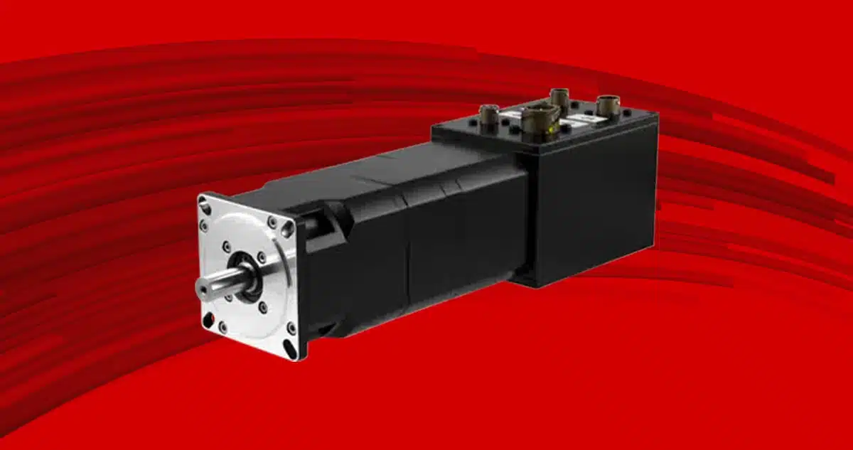
Servotecnica’s offerings include slotted and slotless motors. Slotted motors give high torque density and acceleration results, while slotless motors are excellent for achieving smooth operation with good Kt linearity when used in a servo system.
Cogging torque varies significantly with different motor configurations, and measures are usually taken to reduce its effects, such as tilting the magnets or stator blades. Both technologies offer large rotor bores and can be adapted to low-profile direct drive applications.
The main performance characteristics of each engine type are summarized in the table below.
| Parameter | Slotted | Slotless |
| More uniform motion (low-velocity ripple) | ✓ | |
| Higher torque constant | ✓ | |
| Linearity of torque constant (Kt) | ✓ | |
| Larger through-hole | ✓ | |
| Higher accelerations | ✓ |
Source: Celera Motion