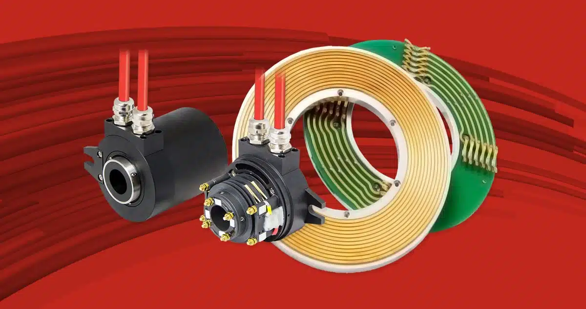
Slip rings are electromechanical devices which continuously transmit power and electrical signals from a static component to a rotating component and vice-versa.Such devices have many names, […]
Slip rings are electromechanical devices which continuously transmit power and electrical signals from a static component to a rotating component and vice-versa.
Such devices have many names, including rotary joints, electric rotary joints, sliding contacts, etc.
It is clear that this solution, with its capacity for continuous rotation, greatly simplifies assembly and does away with the need for complex articulated cabling systems and their associated risk of damage and downtime, thus drastically reducing maintenance requirements.
Depending on the transmission technology, slip rings can transmit power, data or both together; their power transmission capacity ranges from mW to MW, according to the needs of the application and configuration; data can be digital or analogue I/O, including fieldbus data up to 1 Gb/s.
Types of Slip Ring
Given the vast range of uses of slip rings, a variety of contact technologies have been developed which employ diverse configurations and materials. There are currently 4 principal types of contact.
- Conductive block
- Liquid metal
- Fiber brush
- Wireless
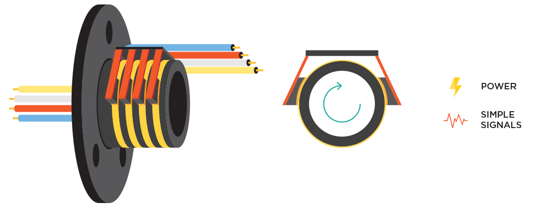
Conductive Block Slip Rings
Conductive block slip rings (also called carbon brush slip rings) are probably the most simple configuration. They are used above all for low technology applications, typically for transmitting power or simple signals. The brushes consist of blocks shaped to contact the rings. The block material may vary from classic graphite for power transmission, to more complex precious metal alloys for signal transmission. The brushes are usually spring-loaded to maintain contact with the rings in case of shock and vibration and to compensate for wear. This technology is subject to a high rate of wear, and requires regular maintenance to prevent conductive dust collecting in the slip ring.
| Pros | Cons |
| High circuit power density | Continuous maintenance |
| Easily customised for mechanical assemblies in-house, since the brushes and rings are available separately | Not suited to complex signal transmission (encoders, fieldbus applications, etc.) |
| Low cost | Sparking may occur in the presence of dust |
| High dynamic resistance variation (noise) | |
| The contact circuits are similar in size to the power circuits |
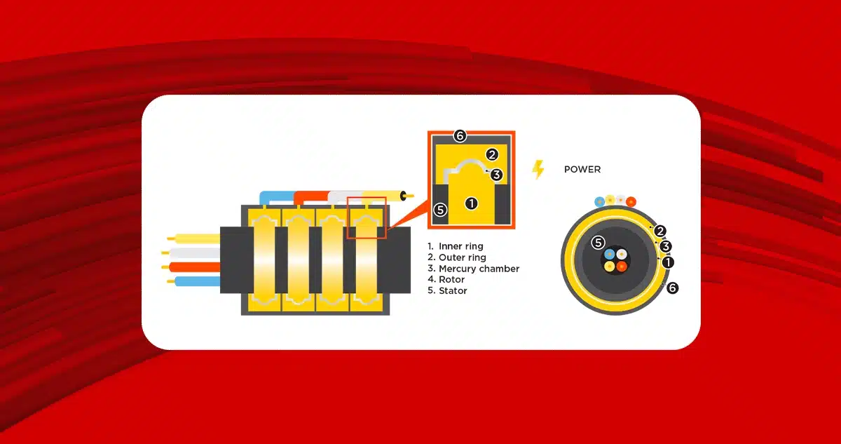
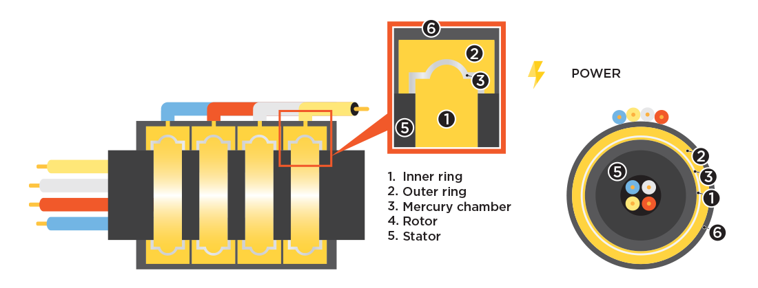
Liquid metal
This used to be the most commonly used type, due to its high performance in a small package. It does not use a brush/ring configuration. Instead, it uses a conductive liquid metal to transmit power and signals between the static and rotary components. Mercury is the most common liquid metal used for this purpose; nowadays, a gallium (Ga) alloy is sometimes used.
However, this technology is used only in a few markets at this time due to the RoHS restrictions on the use of heavy metals, and since the metal is also toxic if it leaks.
| Pros | Cons |
| High current density circuits | RoHS restrictions |
| High electrical current density | Complex configuration with more than 10 circuits |
| Low cost | |
| Maintenance free |
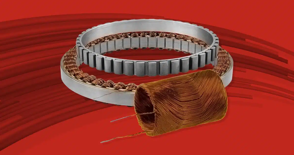
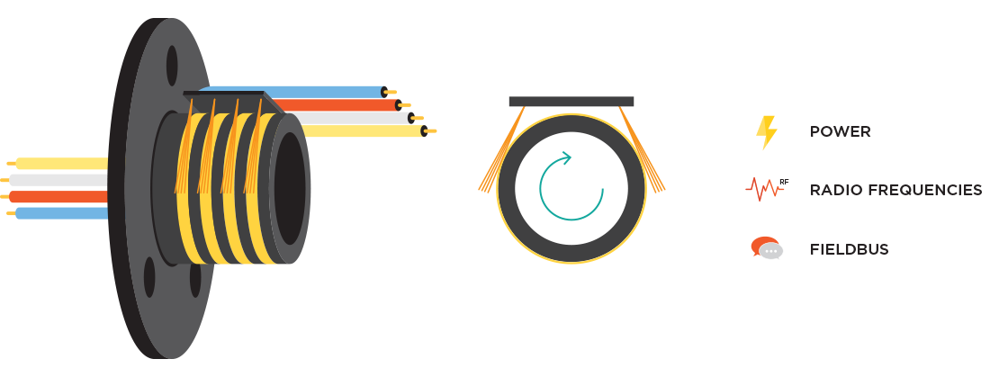
Fiber brush
This is currently the most widely used type due to its great flexibility in use, making it suited to a vast range of applications, from high power transmission to high frequency signal transmission. The brushes may be monofiber for small capsule slip rings (with carcass), or multifiber for larger slip rings. Multifiber brush slip rings offer the best service life and contact quality: wear and dust are reduced due to the low friction between the contacts.
Multifiber brushes are composed of a bundle of thin metal filaments which ensure high contact quality and low wear due to their flexibility. In this case too, as for the conductive block technology, a variety of contact materials and substrates may be used to optimise performance. Alloys of steel and other common metals are usually employed for power transmission, while a tempered gold alloy is used for signal transmission. Gold is used for the latter application due to the fact that it does not oxidise and the quality of the contact is thus not degraded over time.
| Pros | Cons |
| Excellent volume-current ratio | Subject to wear (minimal) |
| Maintenance free | More costly than conductive block solutions |
| High frequency electric signal transmission (up to 10 GHz) | |
| No RoHS restrictions | |
| Low dynamic resistance variation (noise) | |
| No sparking/dust | |
| Complex configurations up to hundreds of circuits |
Wireless/Contactless Slip Rings
Wireless slip rings are a new type of product. They work on the principle of capacitative or inductive coupling for power and signal transmission by exciting the coils at high frequency without contact between the rotating and static components, which can also be separated by special materials if required. In general, they are less efficient than other solutions, and the loss of efficiency is directly proportional to the distance between the coupled components. In reality, this solution is not yet very wide spread. Its main benefits consist in the lack of wear and the possibility of configurations with a high seal/protection rating. On the other hand, they can transmit power only up to 150 W, have low efficiency and they require active electronics to excite the coil. Fieldbus data transmission is generally provided with a Wi-Fi or Bluetooth module integrated into the electronics. This means that each fieldbus connection requires its own module, and if no commercial solution is available it must be developed for the specific application. This type of slip ring may be used in niche applications characterised by high rotational speed and poor access for maintenance.
| Pros | Cons |
| No wear | Low power |
| Maintenance free | Low efficiency |
| High protection rating | Active electronics |
| Poor customisation options |

Summary Table of Slip Ring Technologies
| Type | Power | Signals | Speed | Circuit Density | Lifetime | Custom | Costs |
| Conductive blocks | +++ | + | ++ | + | + | +++ | +++ |
| Liquid metal | ++ | + | ++ | ++ | + | + | ++ |
| Fiber brush | ++ | +++ | ++ | +++ | ++ | +++ | ++ |
| Wireless | + | ++ | +++ | + | +++ | + | + |
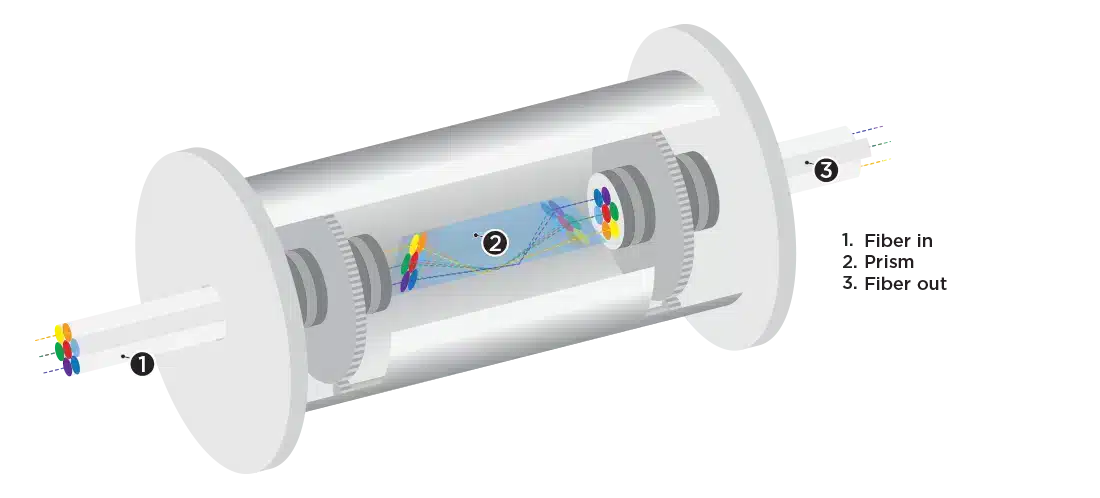
Fiber Optic Slip Rings (or FORJ – Fiber Optic Rotary Joints)
A fiber optic rotary joint is the optical equivalent of an electrical slip ring. These devices enable continuous rotation of one or more optic fibers without affecting the signals transmitted along them. FORJs are widely used in medical systems (OCTs) and in other applications where a twist-free fiber cable is essential.
There are hundreds of patents for two-channel and multiple-channel FORJs, but only a few are commercially feasible.
FORJs are passive components with a specific objective: to optimise signal transmission along optic fibers and minimise losses when one of the two ends is in rotation. The following characteristics are critical in evaluating the quality of a FORJ:
- Insertion loss (IL): as in all transmission lines, there is a loss of power (in dB) caused by the coupling of different materials (including the coupling fluids) or mechanical tolerances of the FORJ. It is clear that a well-designed FORJ must minimise such losses. The IL for a high quality FORJ is around 0.5-1 dB for single channel units and 3 dB for multichannel units.
- Insertion Loss Variation (wow): this is the variation in IL over a full rotation of the FORJ’s rotor relative to its stator. A well-designed FORJ will have a variation per turn of +/- 0.25 dB. The wow may also be used as a parameter in FORJ diagnostics.
- Return Loss (RL): this measures the reflected signal power (from the FORJ to the source of the signal in this case). The RL is just as important as the preceding parameters; this is because nearly all lasers are sensitive to optical reflection, which generates variations in their emission spectrum and hence power jitter. The RL for a well-designed FORJ should be around 60 dB for SM fiber and 40 dB for MM fiber.
For single channel FORJs (whether SM or MM), their relatively simple mechanical construction makes them quite compact in size, while permitting high rotational speed (typically up to 10000 rpm) and excellent reliability, with almost negligible degradation of performance.
The mechanical structure of multi-channel FORJs, on the other hand, is much more complex, and such units must normally be optically aligned manually when very high performance is required.
Although it will not result in complete signal loss, poor alignment has undesirable secondary effects, such as highly wavelength-dependent IL or RL, high PMD (Polarization Mode Dispersion) and high crosstalk (interference between optical channels). A variation in IL of 0.5-1 dB over a wavelength range of 1310 nm to 1550 nm is generally acceptable. In the same way, the PMD measures the elongation of a pulse due to the different transmission speeds of the orthogonal polarization modes. PMD is not a factor for bandwidths under 1 Gbit/s.
Another important factor in the choice of a FORJ is its size. A FORJ is generally incorporated into other rotary components (slip rings, RF rotary joints, etc.) and occupies the centre of the rotary assembly. The size of the FORJ is thus a significant factor in the overall size of the complete assembly. A smaller FORJ will result in a less costly finished system.
FORJs can also be used in submarine applications, where increases in pressure at various depths must be accounted for and compensated. The filling fluid can also be used as a lubricant and to match the coefficients at the rotor/stator interface.
| Pros | Cons |
| Reliable, lossless transmission | High cost |
| High frequency | |
| High rotational speed | |
| Compact size |
The contents of this page are distributed under a Creative Commons Attribution-ShareAlike 3.0 Unported license.