Inductive sensors are often used to measure position or speed, especially in harsh environments. The terminology and techniques used in inductive position sensing can be confusing. […]
Inductive sensors are often used to measure position or speed, especially in harsh environments. The terminology and techniques used in inductive position sensing can be confusing. In this article, we explain the various types of inductive position sensor; their operating principles and their relative merits.
- Introduction
- Type of inductive sensors
- Inductive sensor applications
- Inductive sensors strengths & weaknesses
- New Generation – inductive encoders or incoders
Introduction
Inductive position and speed sensors come in lots of shapes, sizes and designs. All inductive sensors can be said to work using transformer principles and they all use a physical phenomenon based on alternating electrical currents. This was first observed by Michael Faraday in the 1830s when he found that a first current-carrying conductor could ‘induce’ a current to flow in a second conductor. Faraday’s discoveries form the basis of modern electric motors, dynamos and, of course, inductive sensors for position and speed measurement.
Inductive position and speed sensors include simple proximity switches, variable inductance sensors, variable reluctance sensors, synchros, resolvers, rotary and linearly variable differential transformers (RVDTs & LVDTs), and new generation inductive encoders (sometimes referred to as incoders.)

Types of inductive sensors
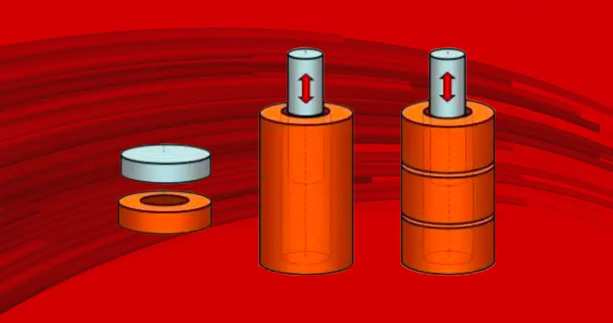
In a simple proximity (or ‘prox’) sensor an electrical power supply causes an alternating current to flow in a coil (sometimes referred to as a loop, spool or winding). When a conductive or magnetically permeable target, such as a steel disk, approaches the coil, this changes the coil’s impedance. When a threshold is passed, this acts as a signal that the target is near. Proximity sensors are typically used to detect the presence or absence of a metal target and the output often emulates a switch. This type of inductive sensor is commonly used where a traditional switch might prove problematic – notably where lots of dirt or water is present. You will see lots of inductive proximity sensors next time you go through a car wash or glance at the landing gear when you board an aeroplane.
Variable inductance sensors and variable reluctance sensors typically produce an electrical signal proportional to the displacement of a conductive or magnetically permeable target (normally a steel rod) relative to a coil. As with the proximity sensor, a coil’s impedance varies according to the displacement of the target when the coil is energised with an alternating current. Such sensors are often used to measure the displacement of pistons in pneumatic or hydraulic rams. The piston can be arranged to pass over the outer diameter of the sensor’s coil.
Synchros are another form of inductive position sensor and they measure the inductive coupling between coils as they move relative to each other. Synchros are normally rotary and require electrical connections to both moving and stationary parts of the sensor (typically referred to as the rotor and stator). They can offer extremely high accuracy and are used in industrial metrology, radar antennae and telescopes. Synchros are notoriously expensive and are increasingly rare, having mostly been replaced by (brushless) resolvers. These are another form of inductive position detector but electrical connections are only made to windings on the stator.
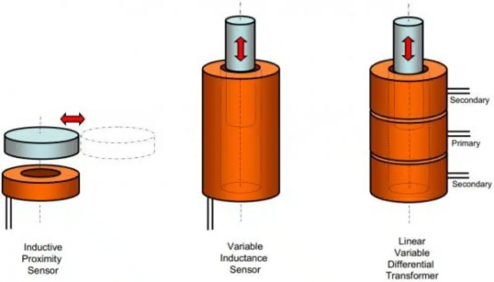
LVDTs, RVDTs and resolvers measure position from the change in inductive coupling between coils, usually referred to as primary and secondary windings. The sensor’s primary winding couples energy into the secondary windings but the ratio of energy coupled into each of the secondary windings varies in proportion to the relative displacement of a magnetically permeable target. In an LVDT, this is usually a metal rod passing through the bore of the windings. In an RVDT or resolver, it is normally a shaped rotor or pole piece that rotates relative to the windings arranged around the periphery of the rotor. Typical applications for LVDTs & RVDTs include hydraulic servos in aerospace aileron, engine and fuel system controls. Typical applications for resolvers include brushless electric motor commutation.
A significant advantage of inductive position sensors is that the associated signal processing circuitry need not be located in close proximity to the sensor’s coils. This allows the sensing coils to be located in harsh environments, which might otherwise preclude other technologies – such as magnetic sensors or optical encoders – as they require relatively delicate, silicon-based electronics to be located at the sensing point.
Inductive sensor applications
Inductive position sensors have a long track record for reliable operation in difficult conditions. Consequently, they are often the automatic choice for safety related, safety critical or high reliability applications. Such applications are common in the military, aerospace, rail and heavy industrial sectors.
The reason for this solid reputation relates to the basic physics and principles of operation, which are generally independent of:
- moving electrical contacts
- temperature
- humidity, water and condensation
- foreign matter such as dirt, grease, grit and sand
Inductive sensors strengths & weaknesses
Due to the nature of the basic operating elements – wound coils and metal parts – most inductive position sensors are extremely robust. Given their solid reputation, an obvious question is ‘Why are inductive sensors not used more frequently?’ The reason is that their physical robustness is both a strength and a weakness. Inductive sensors tend to be accurate, reliable and robust, but also big, bulky and heavy. The need for precision wound coils also makes them expensive to produce – especially high accuracy devices. Besides simple proximity sensors, the more sophisticated inductive sensors are prohibitively expensive for more mainstream applications.
Another reason for the relative scarcity of inductive sensors is that they can be difficult for a designer to specify. This is because each sensor often requires the associated AC generation and signal processing circuitry to be separately specified and purchased. In turn, this requires significant skill and knowledge of analogue electronics. Since younger engineers tend to focus on digital electronics, they will favour alternative, more digital, approaches.
A new generation – inductive encoders or incoders
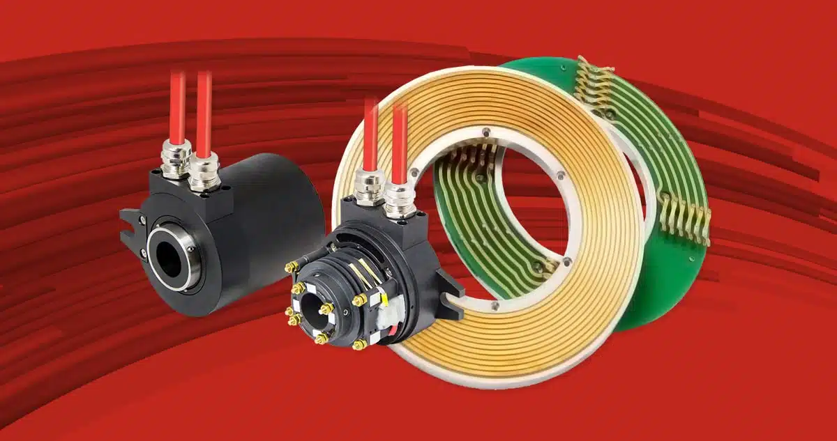
A new generation of inductive sensor has entered the market in recent years and has a growing reputation, in both the traditional and more mainstream sectors. This new generation of inductive sensor is usually referred to as inductive encoder or ‘incoder’ (a mix of inductive and encoder). The approach uses the same basic physics as the traditional devices but uses printed circuit boards and modern digital electronics rather than bulky transformers and analogue electronics. The approach is elegant and opens up the range of applications for inductive sensors to include 2D & 3D sensors, short throw (<1mm) linear devices, curvilinear geometries, and high precision angle encoders, including small rotary encoders & large rotary encoders.
The use of PCBs enables sensors to be printed onto thin flexible substrates, which can also eradicate the need for traditional cables and connectors. The flexibility of this approach – both physically and from the ability to readily provide customised designs for OEMs – is a big advantage
As with traditional inductive sensors, the approach offers reliable and precision measurement in harsh environments. There are also some important advantages:
- Reduced cost
- Increased accuracy
- Reduced weight
- Simplified mechanical engineering, for example, eradication of bearings, seals & bushes
- Compact size – notably with stroke length compared to traditional LVDTs.
- Simplification of the electrical interface – typically a DC supply and absolute, digital signal.
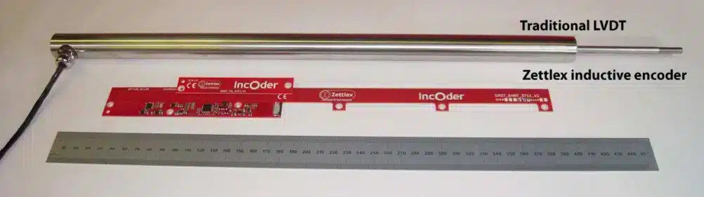
his is nicely illustrated in the above image – showing a traditional 150mm stroke LVDT and its new generation replacement, which has been produced for a manufacturer of linear actuators. The parallels to the ‘before’ and ‘after’ dieting photographs are obvious. This is reinforced when one considers that the new generation device also includes the associated signal generation and processing circuit (not shown with the traditional LVDT). By way of comparison, the Zettlex device offers:
- U>10 fold increase in accuracy
- 95% weight saving
- 75% reduction in occupied volume
- 50% cost saving
- Gdirect generation of digital data – thus eradicating the need for analogue to digital conversion