One of the most common ways to move a load from point A to point B is to by means of linear translation using a worm […]
One of the most common ways to move a load from point A to point B is to by means of linear translation using a worm screw and spindle nut. The purpose of this article is to discuss the basic principles of linear actuators, with the aim of helping you to select the best solution for your application.
Let’s start with some basic points about design:
- What is the system load?
- What is the speed at which the load is to be moved from point A to point B?
- What is the distance between the two points?
- What is the time within which the load is to be moved from point A to point B?
- How precise must the application be?
- How repeatable must the application be?
- Is the stroke vertical or horizontal?
Basic concepts
Lead v. screw pitch
The pitch is the axial distance between threads. The pitch and lead are the same thing in a single start screw. A single screw may have multiple threads (otherwise known as starts). Multi-start screws generally offer more stable and efficient power transmission. The DINGS’ catalogue uses the term “lead” to specify screws, since the lead is the linear stroke per turn of the screw. The greater the lead, the longer the linear stroke per turn of the screw.
Load
Generally specified as kg to be moved, or kgf (thrust).
Speed [V]
Generally specified as millimetres per second (mm/sec). This expresses the speed of the actuator’s linear stroke.
Distance
Generally specified in mm, it is the total stroke of the application.
Time (T)
Generally specified in seconds. The period of time required to cover a certain distance, it determines the speed, acceleration (A) and deceleration required to reach the target position.
Vertical or horizontal application
If unpowered and not equipped with a brake, vertical applications may be subject to back-drive. When calculating the load / force of vertical applications, one must also take gravity into account.
The precision of the screw
This is expressed as a value per a certain length of the screw. For instance: 0.015 mm x 25.4 mm length. The precision of the lead is the difference between the actual stroke and the theoretical (nominal) stroke.
For instance, a screw with a lead of 1.27 mm and a lead precision of 0.102 mm x 304.8 mm, when turned 24 times, will move the load by a nominal stroke of 304.8 mm. However, since the lead precision is 0.102 mm per 304.8 mm, the effective stroke will be in the range 304.6984 mm to 304.902 mm.
Total radial oscillation
The amount of oscillation normal to the central axis of the screw.
Repeatability
The repeatability of the system (with regard to the precision of the screw) is a critical factor in the majority of motion control applications, as it enables them to reliably reach a given control position. For instance, a repeatability of ± 0.127 mm means that if we repeatedly move the load to a given target position, the linear error will not exceed ± 0.127 mm.
You will find a discussion of repeatability and precision in this article on Zettlex encoders.
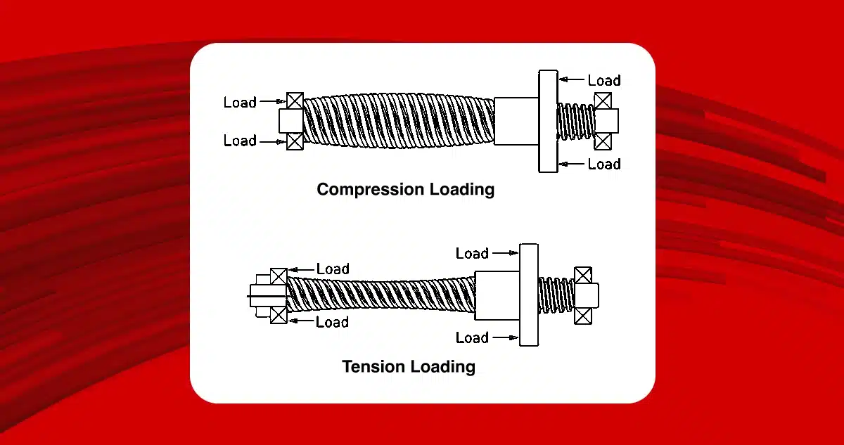
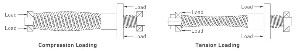
Tension or compression load
A load which keeps the screw under tension is called a tension load.
A load which keeps the screw under compression is called a compression load. Depending on the size of the load, the design of a screw under tension is based on its tensile strength rather than the axial loading of the screw.
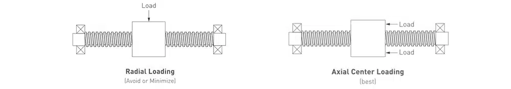
Radial load
A load perpendicular to the screw. They are not advisable, unless a supplementary assembly is used to support them, like a linear guide.
Axial load
A load applied along the centre axis of the spindle nut.
Static load
The maximum axial load – including impact loads – applied when the screw is not rotating.
Dynamic load
The maximum recommended axial load applied when the screw is turning; this component is often dominated by inertia and acceleration.
Back-drive
Back-drive is the effect of the load’s axial thrust on the screw or worm which generates the rotary motion. A worm with an efficiency of more than 50% generally has a tendency to back-drive, which can be avoided by choosing a spindle nut with an efficiency lower than 35%. The smaller the lead, the more back-drive or free rotation is reduced. Vertical applications are more subject to back-drive due to the effect of gravity.
Torque
The motor torque required to drive only the spindle nut is obtained by summing:
the inertial torque + the resistance torque (friction between the worm and the moving screw) + the torque required to drive the load
Lubrication
The worm nut contains self-lubricating material which makes additional lubrication of the system unnecessary. Teflon coating the screw also reduces friction and increases the service life of the system.
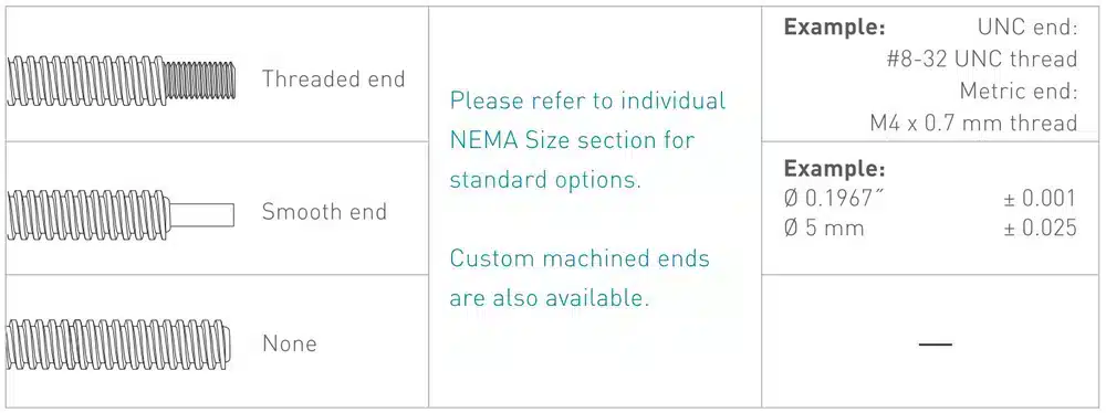
The machining of the ends of the screw
This can be done in accordance with the Imperial or standard metric system. Custom machining is also available on request.
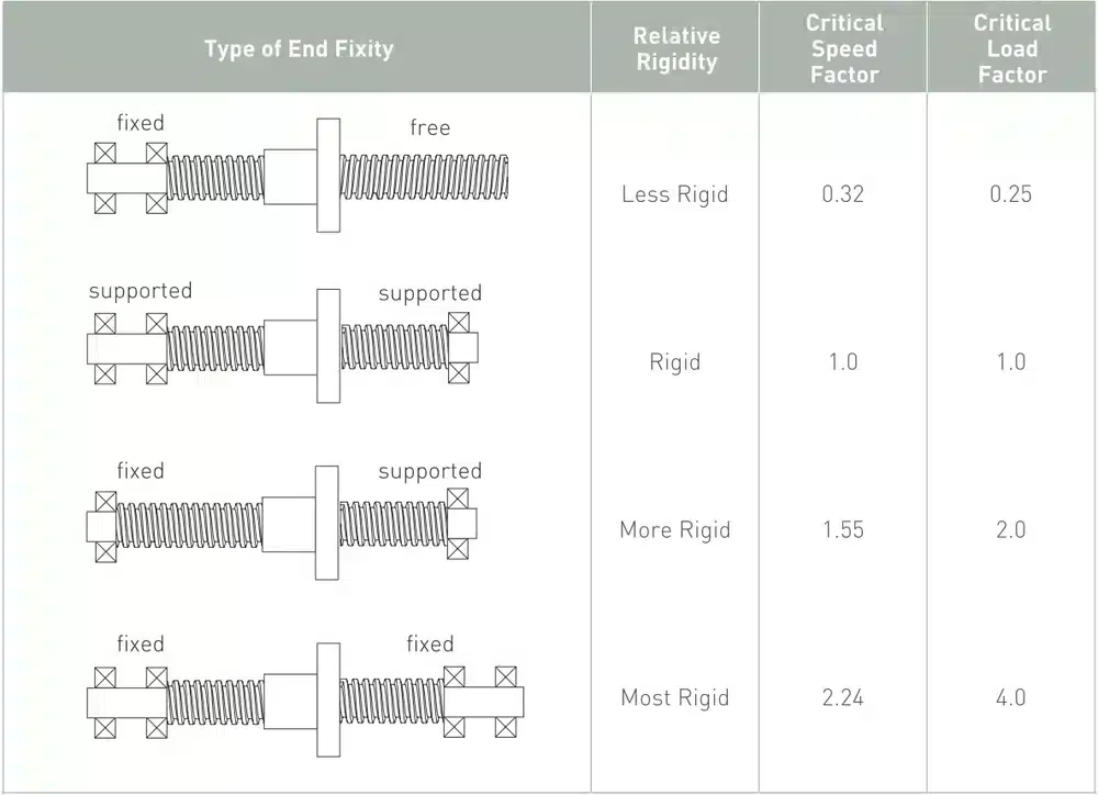
Stability
The mounting and support of the ends of the screw influence its performance (speed and efficiency).
Axial resistance
When a compression load is applied to a screw, its elastic stability limit may be exceeded, thus damaging the screw due to instability or flex.
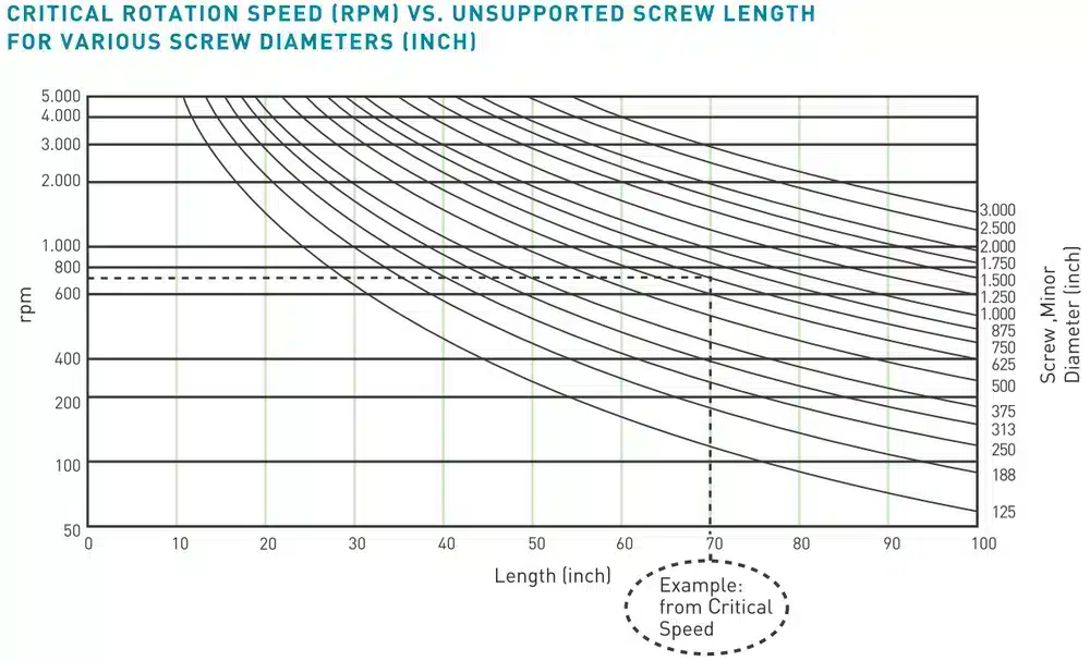
Critical speed
The critical speed is the rotational speed of the screw at which the first resonant harmonic frequency due to flexing of the screw itself is reached. The system is subject to vibration and instability at this speed. A variety of factors determine how quickly the system reaches its critical speed:
- the pitch of the screw
- its rotational speed
- the stability of its ends
- the axial load
- the diameter of the screw
- the tension or compression load
For instance, the following graph shows that the critical speed threshold of a screw of diameter 3/4” and length 70” is 700 rpm.
Mechanical backlash
The backlash is the relative axial movement between the screw and the worm nut when they are not working. It is normal that the backlash increases as the system wears over time. The backlash can be compensated or corrected by installing an anti-backlash worm nut. Backlash is generally only an issue in cases of bi-directional motion control.
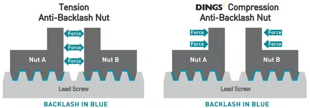
Anti-backlash worm nuts available on request
Types of linear motion control systems
- Non captive
- External Linear
- Captive

Why choose one form factor over another?
You should ask yourself the following questions:
- Which mechanical solution is best adapted to the application?
- What type of screw mounting is required?
- Is it acceptable for the screw to rotate?
- Does the application require an encoder or brake?
- What is the stroke of the application?
Which environmental parameters should be considered?
DINGS’ Motion linear motion control systems are designed for use in dry, non-corrosive conditions. The standard products are not IP protection rated. Using non-IP rated linear systems in corrosive, dirty environments greatly reduces the service life of the product.
Temperature
Very high or low temperatures can greatly affect the worm nut, thus changing the resistance of the system.
Maximum dynamic load
Each NEMA motor size is rated for a maximum dynamic load which must not be exceeded.
For details, refer to the speed/force curves for the individual sizes.
Choosing the motor
Several factor effect the appropriate combination of motor and spindle nut:
- How much force is required?
- What is the necessary pitch angle?
- Are they any residual or holding force requirements?
- Are there limitations to the physical size of the assembly?
- What type of driver (amplifier) is used?
A guide to choosing the right product
To reduce the complexity and cost of design, it is essential that the motor/spindle nut combination be properly sized. We provide a standard procedure below for selecting the components required for an application:
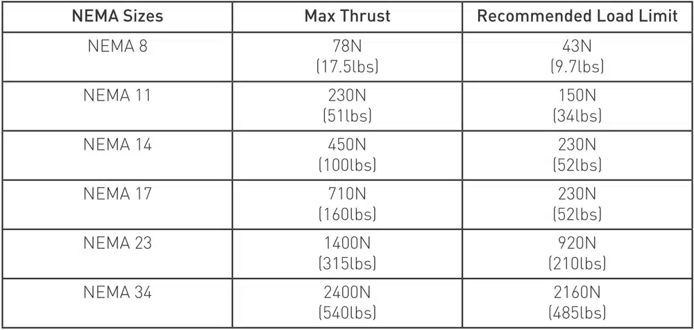
Step 1 – Select the NEMA motor size (force requirements)
The table shows the output thrust per NEMA size: as the motor’s NEMA size increases, so does the thrust delivered by the actuator.
Step 2 – Select the screw lead (force and speed requirements)
After you have estimated the thrust and NEMA size suited to the application, you must select the screw lead, bearing in mind the speed and acceleration of the load.
The very nature of spindle nuts makes the speed and output thrust deliverable by the motor/spindle nut combination inversely proportional to each other. It follows that high speed applications will have a lower output thrust.
While the above steps provide a reliable basis for effectively choosing a motor/spindle nut combination, other variables must also be considered, including:
- Duty cycle
- Required service life of the system
- Environmental factors
- Positioning repeatability
- Acceptable backlash
- Acceleration/deceleration requirements
- Specifications of the driver
- Vertical/horizontal orientation
Given the numerous variables involved in choosing the motor, we strongly recommend running practical tests to determine the specific combination of motor and spindle nut demanded by the application.
IMPORTANT: Despite the rough guide to choosing the optimal motor/spindle nut combination provided in this article, we strongly recommend that you contact our application designers for assistance in selecting the motor.
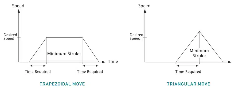
Motion profiles: trapezoidal v. triangular
These are the most commonly used motion profiles. Other motion profiles may be employed, depending on the time and stroke specifications of the application. The area under the curves in the following graphs represents the minimum stroke of the linear actuator.